
Over the years, there have been many expensive and notorious incidents that have prompted the necessity of cyber-physical security of manufacturing plants. Stuxnet, Duqu, Flame, and Gauss were malware specifically designed to target industrial control systems (ICS) and cause physical damage to the equipment and inhibit processes from executing normally. In the case of the Stuxnet disaster, which degraded the integrity of uranium centrifuges, and prompted their destruction through software, while inhibiting security measures and monitoring software from accurately displaying the current situation of the machinery. As a result, the centrifuges were led to spin at unusually high rates, destroying the plant (Chipley, WBGD;). Because of incidents like these, respondents to the Global State of Information Security Survey - 2016 reported budgets for cyber-physical security to have increased by 24 per cent that year alone, suggesting a robust recent trend in the general industry towards prioritising the security of software and network (Williams, COPA-DATA UK;). Although many competitors in the industry have decided to invest more in cyber-physical security, many control systems currently used in the professional world were installed over twenty years ago. The old systems are opting out of reinstalling and migrating control systems due to financial costs but opening them up to several security risks. This realisation has prompted a more open study of continuous pharmaceutical manufacturing and CPS logic for this more experimental system, which holds a high initial investment. Still, it serves as a modern investment that can replace the outdated hardware currently being used.
According to the Business Advantage State of Industrial Cyber Security 2017 Report, 54 per cent of companies in the survey experienced some cybersecurity incident in their control system within the past twelve months, with 16 per cent claiming more than two incidents, prompting the necessity of a network monitoring and autonomous response system, in addition to localised software installation. Within the pharmaceutical manufacturing industry, the integrity of the compound often depends on the precise and consistent regulation of hundreds of parameters, from feeding, mixing to compaction. Pharmaceutical plants are now becoming the most targeted facilities for attacks, acting as a delicate system with great consequences for global safety, as well as holding incentive for attackers with invaluable formulas for drug manufacturing. Even minor parameter alterations can result in a wide variety of disruptions, ranging from inefficiencies like production downtimes or more damagingly, poisonous drug distribution, and hazardous waste handling (Perelman, Indegy). Especially due to the direct impact on public safety and health as an ingested medical compound, tablet production holds many legal and moral restrictions, prompting high-grade security to ensure the integrity of machinery and products.
In the continuous manufacturing process, tablets are produced continuously, and product quality relies on real-time monitoring and implemented control systems. However, the attackers can modify and collect information from PLC (programmable logic controller) communication without directly accessing to HMI (human-machine interface). If the attack happens at the PLC level, it means the attacker could directly control all the unit operations and devices that are connected to the PLC system. Therefore, it is necessary to monitor data directly from the data block instead of collecting data from other sources that could be infected by cyber-physical attacks. There are existing data capturing software that can access data from HMI memory block, like Snap 7. However, after accessing data from the memory block, it is not readable for operators to understand which parameter has a potential problem in the CM process. Therefore, an advanced tool is needed, which can access the data blocks, decode it quickly, and take the security actions in real-time. Such a software tool has been developed in this work, and its applications have been demonstrated.
PLC is a server connecting plant and the host operating PC (a control platform). For PLC system, security is the main concern because the information and data flow is not under direct supervision of the operators. Supervisory control and data acquisition (SCADA) is one of the most commonly used systems for controlling and monitoring the data. The continuous manufacturing plant considered for this study is for drug production, and the plant uses both SCADA and PLC. In the process of producing drugs, eliminating the cybersecurity threat is essential because the attacker could counterfeit the pharmaceutical drugs by gaining confidential information relating to the formulation as well as qould affect the CQA’s.
In this work, a systematic framework, including the methods and tools, have been developed for proactive identification and mitigation of potential cyberphysical attack risk on the continuous pharmaceutical manufacturing process. We applied the cyber-physical securityrelevant software tools such as Snap 7, Wireshark, and Tripwire to CM plant. We have developed a software tool named CPS (Cyber-Physical Security). The developed tool is complementary to the existing tools, and it should have a broad range of applications in the cyberphysical security of the continuous pharmaceutical manufacturing process.
The rest of the paper is organised as follows. The systematic cyber-physical security framework is described in section 2. The functionality of the developed CPS tool is presented in section 3. The integration of the CPS tool with the plant is explained in section 4. Building the security database is presented in section 5. The applications of the CPS tool are demonstrated in section 6 through a case study. The future expansion of the CPS tool is described in section 7. Finally, the manuscript is concluded in section 8.
The systematic cyber-physical security framework
Overview of the cyber-physical security system of the continuous pharmaceutical manufacturing plant
As shown in Figure 1, the PLC is in the server that controls communication between devices and the host PC in the continuous pharmaceutical manufacturing plant. Therefore, the PLC is vulnerable. If any hackers want to gain access to the continuous manufacturing plant, PLC could be the best target for them. Therefore, the priority for protecting the continuous pharmaceutical manufacturing plant is to monitor the status of PLC to detect suspicious activities. The data and information flow from the plant to the human-machine interface (HMI) via multiple layers, and a data breach could happen at any of these layers. The conditions of the continuous pharmaceutical manufacturing plant usually are monitored manually through the HMI of the operating PCs assuming that all the intermediate communication layers are secure. However, in the case of the cyber-physical security risk, HMI has limits in monitoring data from PLC data blocks. For example, any modification in the plant operating set points that may have severe consequences on plant safety, and the operator cannot easily detect the product quality via the currently available cyber-physical security system. Therefore, it is necessary to have the CPS tool to monitor and secure the continuous pharmaceutical manufacturing plant.
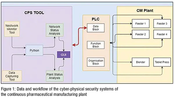
As shown in Figure 1, the proposed CPS tool developed in the Python programming platform integrates the network monitoring tool and data capturing software with the CM plant via PLC. The network monitoring tool (e.g., Wireshark) gives the real-time status of the data traffic communicating from operating PC to the plant and vice versa. It thereby detects the unauthorised access of the plant. The data capturing tool (e.g., Snap 7 integrated with CPS tool) detect any changes in the data communication with the plant and thereby prevent any unauthorised alterations in the plant operating parameters. We developed a graphical user interface (GUI) to ensure the users to use the tool efficiently.
In the PLC architecture (see Figure 1, middle), data of the PLC is stored into the data block. The function block is for storing the function, the organisation block stores all function block and data block of the process. The PLC is connecting different unit operations (e.g., feeders, blender, tablets press) of CM plant with control platform.(Figure 1)
The architecture of cyber-physical security (CPS) tool
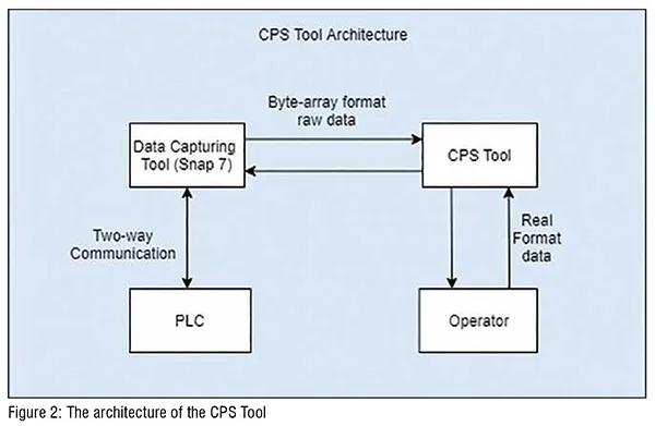
The architecture of the CPS tool is shown in Figure 2. As shown in the figure, the CPS tool integrates the data capturing tool, such as Snap 7. When ‘the raw data’ (in byte-array format) is getting communicated from ‘PLC Data Block’ to HMI, then the data capturing tool is monitoring it in real-time. However, the raw data is in byte array format, and the operator cannot understand it. Therefore, taking any security action either by the control system or operator is not possible. So, after capturing the ‘raw data,’ the next step is to decode it using the developed CPS tool. The CPS tool can also read and write in the data block; thereby it can take proactive cyber-physical security action in real-time. (Figure 2)
A systematic methodology for cyber-physical security
Proactive detection of cyber-physical attack risk
The systematic methodology for proactive detection of the cyber-physical security risk is shown in Figure 3. The data block is the unit in the control system that stored all the information in a coated form. The information/data stored in the data block directly goes to the plant when the function block uses them. In other words, all the changes (authorised/ unauthorised) can only be implemented in the plant through a data block. Therefore, it is a unique place where the security system can be placed to screen the authorised and unauthorised activities. So, if this information/data stored in the data block can be decoded in real-time, then it is possible to proactively detect any attempt to make the unauthorised changes in the plant. In this way, the cyber-physical attacks can be identified and mitigated before it impacts the manufacturing process and product quality. The developed CPS tool is precisely performing these tasks, as described in subsequent sections.
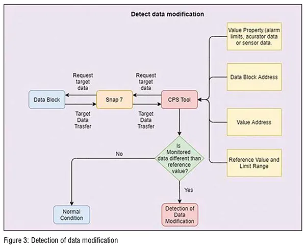
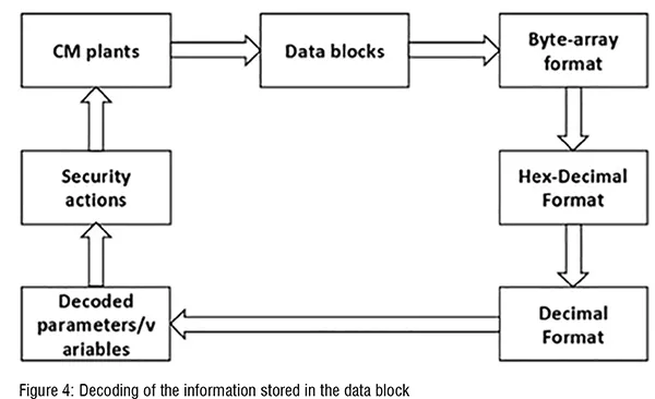
As shown in Figure 3, the starting point is to provide the required inputs to the CPS tool. These inputs are data block address, reference value, the acceptable limit ranges, and other properties, as shown in the figure. The Snap 7, then scan the data block in real-time. The developed CPS tool decodes the data block to get the ordinary numbers (integer format) that can be understood by the operator and programmer (see Figure 4). The decoded number is then compared with the pre-specified reference value. If the actual value is the same as the reference value or within the specified limit range, then no security action is taken. Otherwise, the CPS tool will take the appropriate security actions, as discussed in the next section. (Figure 3 & 4)
Cyber-physical security actions
The systematic methodology for cyberphysical security is shown in Figure 5. If any plant data get modified, then the ‘cyber-physical security (CPS) tool’ will take the actions according to the flowchart shown in Figure 5. All the purple blocks in Figure 5 referred to operations in the security system.
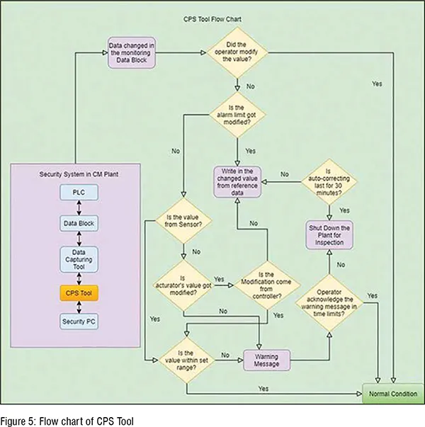
As shown in Figure 5, the plant is connected with PLC. The data coming from or going to the plant is stored in the ‘data blocks,’ which is monitored in real-time using developed CPS tool. The CPS tool should be placed in a security PC, which ideally need to be a separate PC to avoid getting infected if the operating PC may get infected. The CPS tool detects any changes in the data in real-time directly from the data block (see Figure 3). Subsequently, a pop-up window is generated to check if this change in the data value is intentionally made by the operator or not. If the operator acknowledges making this change, then it means the operation is regular, and no security actions need to be taken. If the operator has not made the changes, then the security actions will be considered as described in subsequent paragraphs. Note that if the operator does not respond, then the CPS tool will assume that the change has not been made by the operator, and therefore, the appropriate security actions will be initiated.
If the change is not made by the operator, then the next step is to check whether the changed value is within the specified limits or not. If it is outside of the limits, then the CPS tool will auto-correct it by writing the original value of the data. Note that, for repeated changes, the CPS tool will keep on correcting it for a specified period of the time (e.g., 30 mins), and then if the problem still exists, then it will shut down the plant for manual inspection and fault detection.
If the change is within the acceptable limits, then the next step is to find out whether this data is coming from the sensor or not. If the data is not coming from the sensor, the next step is to identify the data belongs to the actuator or not (the signal that goes to the plant). If the data belong to the actuator, then the CPS tool will autocorrect the value irrespective of the magnitude of the changes. The reason is that the signal going to the plant is supposed to be constant unless it is intensionally changing because of the control actions. If the actuator value is coming from the controller, then the next step is to check if the actuator value is within the specified limits or not. If it is within limits, then no action is needed; otherwise, the CPS tool will generate a warning message. If the operator acknowledges the warning message, then no more operation will be taken; otherwise, the CPS tool will suggest the operator shutting down the plant for inspection and fault identification.
If the CPS tool detects that the monitored data is coming from a sensor, but the changes are within the acceptable range, then no security actions will be taken. If it violates the limits, then the CPS tool will generate a warning message. If the operator acknowledges the changes, the CPS tool will not take any security action. Otherwise, the CPS tool will shut down the plant for inspections and further investigation as required to determine if it was a false alarm. Note that the operator can specify the time for which the CPS tool should wait before shutting down the plant, which means that the CPS tool does not need to shut down the plant instantaneously to avoid any mechanical damage in the plant. (Figure 5)
Functionalities of CPS tool
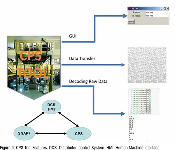
CPS tool is for monitoring security data during the manufacturing process. The CPS tool integrates the data capturing software by importing its library. However, since the data format collected from the data capturing software is in byte array format, decoding data from the data block is the first step. CPS Tool has three functionalities (Figure 6): the graphic user interface (GUI) for allowing the operator to input their system’s IP address, plant, and control system information (data block address in use). Collect raw data in a data block with an Ethernet connection. The CPS tool is capable of decoding raw data to floating-point data for better understanding the data to monitoring specific data block. (Figure 6)
It is necessary to create a GUI to create a user-friendly environment for non-programmers. After entering the IP address of the plant and the DB address that the operator wants to monitor, it is clicking the ‘Connect’ button that will allow the CPS tool to access data and track the data in the CM process.
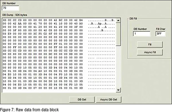
By default, the HMI should be the only way to communicate with PLC. Any other methods that can access to the PLC would be considered as security concerns. Data capturing tool is one way to communicate with PLC. The raw data from the data capturing software does not show much information to the operator without decoding (see Figure 7). Therefore, decoding byte arrays type of data into an understandable format (real number) is necessary. The next steps after decoding the byte array format raw data are storing the decoded values into the CSV files for references and mapping the decoded value from the CPS tool with physical properties. (Figure 7)
CPS tool connected with CM Plant
The CPS Tool continuously scans the data blocks, decodes values in datablocks, and provides the actual value of the critical process parameters. After the operator sets up the limits for the monitoring parameters, if the monitoring value is out of the set range, a warning message will be displayed. Comparing with the HMI tool’s monitor function, the CPS tool’s monitoring function is mainly focused on the cybersecurity side. The main distinguishing feature of the CPS tool is the function of monitoring alarm limit changes.
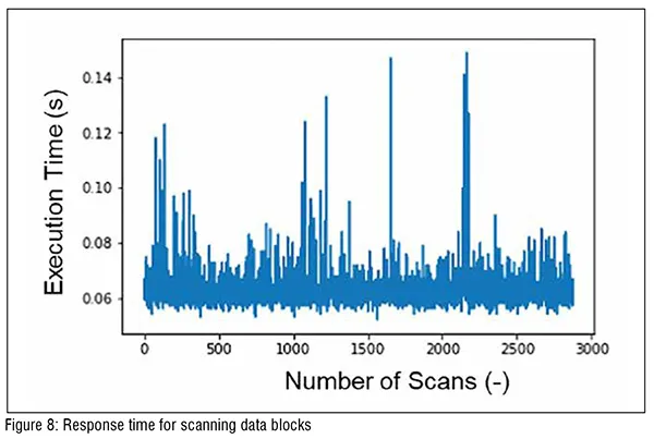
The next rising question about the CPS tool is the response time to scan one data point form the targeted address in the data block. Figure 8 shows the response time for reading data from a single address in a single data block. On average, the CPS tool takes 0.063 seconds to scan and decode one raw data point. The response time is measured by collecting data of one address in data block 71 (tablet press). Therefore, if the attacker modifies the value in this specific address, the CPS tool will detect unauthorised changes within 0.063 seconds. However, the response time varies from different data blocks, which means that it might take longer to read another data block. (Figure 8)
Depending on which parameters the operator is monitoring, the setup of the reference value would be different. The CPS tool sends the warning messages in IDE when the tablet press is in resting condition (see Figure 9). Fill depth and production rate values read from the data block using the CPS tool. When the CPS tool detects the value is out of set limits (The filling depth has a set limit of 15.0, and the production rate has a set limit of 100), the CPS tool displays many warning messages for alerting the operator.
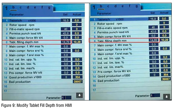
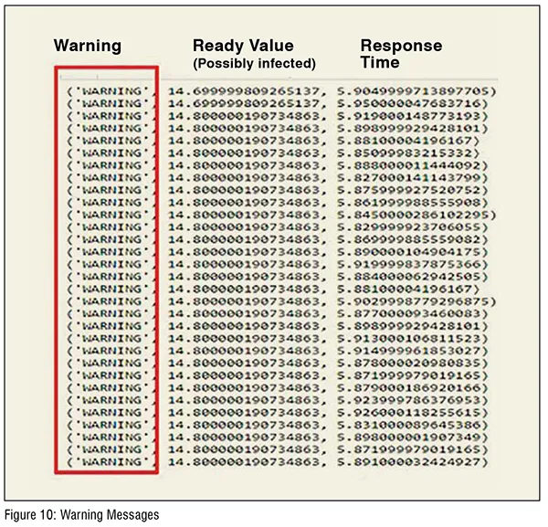
In the CM plant, we performed the experiment about monitoring the tablet fill depth value. We changed the tablet fill depth with HMI in the CM plant and confirm if the CPS tool can detect the modification. In figure 9, the value of table fill depth modified from 14.70 to 14.80. The reference value set in the CPS tool is 14.70 and it detects the modification and sent out the warning message to alert the operator as in figure 10
Storing data into the database
It is important to keep tracking data in real-time by using the CPS Tool. For future reference purpose and regulatory perspective, implemented features in the CPS tool for allowing the operator to save all the monitoring data. The historical data is useful for offline investigation of cyber-physical security to ensure that the plant was not running under attacks at any time interval. The historical information is also helpful to determine if it is necessary to disregard the products which are suspected to be influenced by cyber-physical attacks. For example, when the CPS tool will notice the critical parameters of the tablet press like fill depth, or main compression force is out of range. The CPS tool will generate the warning message, value of the variable, and corresponding time. The actual value recorded from the machine has multiple variables like flow rate or ingredients of the powder that will cause fluctuation and impact the accuracy for determining safety status in the plant. Therefore, a warning message might have false alarm issues, and the operator could not correctly interpret if the situation was outside attacks or not. For having data saved after the operation, if the operator saw many warning messages, then the operator can have reference data set to analyse the suspicious data changes and identify if the situation is a false alarm or actual attacks.
Security concerns regarding with alarm limits modification
The alarm limits are critical in the role of alerting the operator about unexpected situations happening in the CM plant. However, if attackers modify the alarm limits setting, no warning message will be displayed. The reason is that the alarm condition in the previous environment is masked too safe now. Therefore, it is necessary to have a side tool for continually monitoring the alarm limits situation. The Figure 5 shows the flow chart about detecting modification of alarm limits. The alarm limits value does not change during the manufacturing process, unlike other actuator values.
CPS Tool user interface for value property and alarm limit inputs
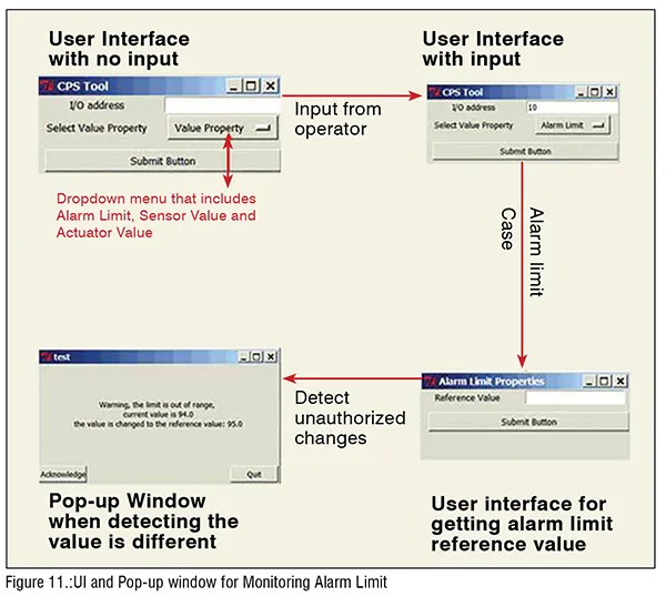
Before the monitoring process, the operator needs to enter the relevant information about the value that need to be monitored (see Figure 10). The relevant information would be value’s property, which is the alarm limit. In this experiment, the reference value is 95, and the I/O address of the monitoring value is address number 10. We developed a GUI, as shown in Figure 11. The GUI allows the user to enter the value’s address and the category of monitoring value. Value property is in the form of a dropdown menu that contains ‘Alarm Limit,’ ‘Actuator Value,’ and ‘Sensor Value.’ After entering both the I/O address and the value property in the GUI, the user needs to click on ‘Submit Button’ and close the window. Then, the next window will pop up, depending on which value property is entered. In this experiment, the monitoring value’s I/O address is 10, and the value belongs to the alarm limit category. The alarm limit properties’ window will pop up and ask the operator to enter the reference value, which is 94.0 in this case. After all, based on the inputs that the operator provides, the CPS tool will show the pop-up window as a warning to the operator if the CPS tool detects any modification in the manufacturing process. Since the value property is ‘alarm limits’ in this case study, the CPS tool will also auto-correct the modified value to the reference value. (Figure 11)
An experiment of monitoring alarm limits
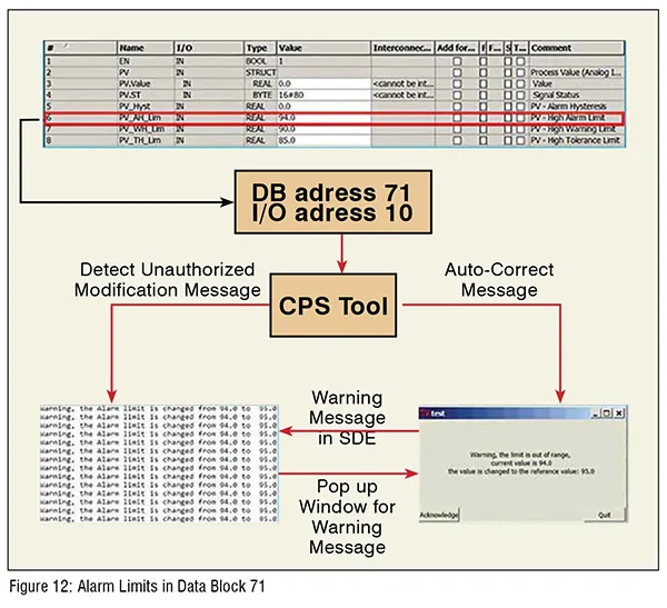
In this experiment, the targeted data block number is 71, and the main focus is to detect any modification in the data block 71’s alarm limit setting (upper alarm limits’ I/O address in DB 71 is 10). There are two alarm limits in data block 71: one is the upper bound, and the other one is the lower bound. If the monitoring value got out of range, which means the monitoring value is higher than the upper bound or lower than the lower bound limit. Then the CPS tool will display a warning message to alert the operator.
Figure 11 shows the flow chart of the monitoring alarm limit experiment with the CPS tool. In this experiment, the upper alarm limit is modified from 94.0 to 95.0. The CPS tool is monitoring the single address (address 10), which is the upper alarm limit in DB 71. If it detects any changes in the upper alarm limit, it will send a warning message and auto-correct the current value to reference value. (Figure 12)
Possibilities of integrating with other tools
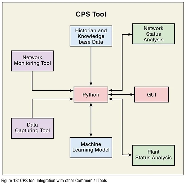
We developed the CPS tool using Python as the programming language. Cyber-physical security has multiple areas, including network status, machine learning for data analysis, etc., (see Figure 13). The CPS tool can integrate other functions by implementing existed packages from Python with modification for cyber-physical security purposes. In continuous manufacturing security, multiple devices are working in a single process. Therefore, it is necessary to have a tool for monitoring data and analyse the correlation of data from various devices. Flexibility is critical to implement into the numerous platform, and the CPS tool is capable of fitting into different platforms. After reading multiple devices’ data, running a machine-learning algorithm to them will reveal more accurate results for detecting attacks. The most popular programming language for machine learning is Python, which is also used in the CPS tool. For this reason, the CPS tool can enable further enhancements with integrating machine learning algorithms. (Figure 13)
Machine learning models are usefulfor continuous manufacturing process analysis. In the current state, only the hard limit which is set by the operator is implemented in the CPS tool. However, the hard limit has limitations in handling cyber-attacks because values might get masked and hard limit is not suitable for dynamic analysis. To perform dynamic analysis, creating the soft limit concept is the critical step (see Figure 14). The soft limit is the limit set by using multiple parameters instead of the targeted parameter as reference. Therefore, even the targeted setting is masked; the soft limit is still consisting of the original configuration. (Figure 14)
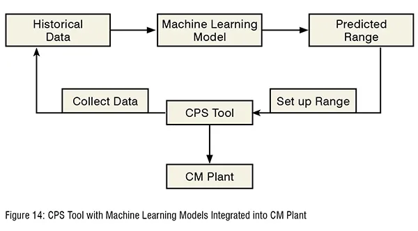
The CPS tool plays a role in monitoring any suspicious data which are out of soft limit and collect data in every operation if needed. Saved data from the CPS tool is used as input for training machine learning model. The machine learning model sets up the soft limit when the operation is going on. The soft limit will improve detecting malicious attacks with masking values because the masked value is out of range by prediction of other values.Conclusions
A distributed control system has significant impacts on the increasing productivity of the manufacturing plant. However, not paying enough attention to the cyber-physical security side in the manufacturing process would cause severe damages to the plant and clients. To monitor data in the plant, a cyberphysical security (CPS) tool has been developed. The CPS tool’s applications have been demonstrated in continuous pharmaceutical manufacturing pilotplant. Implementing various features in the CPS Tool, including data monitoring and data storage, helps the operator to detect unauthorised modifications in the manufacturing process. The time requires to read data from a single address in a single data block is considerably shorter. With the ability to access the data from the data block, ‘monitoring alarm limits setting’ become the main difference in comparison to the existing HMI tool. The developed CPS tool is complementary to the existing tools. Therefore, it should have a broad range of applications in various manufacturing industries. The integrated commercially available and developed (in house) cyber-physical security tools have added an extra layer of security of continuous pharmaceutical manufacturing pilot-plant for any unexpected attacks.
Acknowledgments
This work is supported by the National Science Foundation Engineering Research Center on Structured Organic Particulate Systems (C-SOPS), U. S Food and Drug Administration (FDA), and Rutgers research council.
References:
1. The Spear to Break the Security Wall of S7CommPlus
2. https://www.blackhat.com/docs/eu-17/materials/eu-17-Lei-The-Spear-To-Break%20-The-Security-Wall-Of-S7CommPlus-wp.pdf (last visit 07/01/2020)
3. P. W. Singer, “Stuxnet and Its Hidden Lessons on the Ethics of Cyberweapons”
4. Boldizsar Bencsath, Gabor Pek, Levente Buttyan, and Mark Felegyhazi. “The Cousins of Stuxnet: Duqu, Flame, and Gauss”
5. “The Industrial Cybersecurity Imperative,” Paul Miller, https://www.arcweb.com/blog/industrial-cybersecurity-imperative (last visit 07/01/2020)
6. “The State of Industrial Cybersecurity 2017”. https://go.kaspersky.com/rs/802-IJN-240/images/ICS%20WHITE%20PAPER.pdf (last visit 07/01/2020)
7. Singh, R., Sahay, A., Karry, K. M., Muzzio, F., Ierapetritou, M., Ramachandran, R. Implementation of a hybrid MPC-PID control strategy using PAT tools into a direct compaction continuous pharmaceutical tablet manufacturing pilot-plant. International Journal of Pharmaceutics. 2014b; 473, 38–54.
8. Roberts, S. J. (2014). The Necessity of Information Security in the Vulnerable Pharmaceutical Industry. Journal of Information Security, 05(04), 147–153. DOI: 10.4236/jis.2014.54014
9. R. A. Kisner, W. W. Manges, L. Macintyre, J. J. Nutaro. Cybersecurity through Real-Time Distributed Control Systems. https://www.researchgate.net/publication/241963059 (last visit 07/01/2020)
10. Snap 7 and PLC. http://snap7.sourceforge.net/ (last visit 07/01/2020)
11. Y. Wang, J. Liu, C. Yang, L. Zhou, S. Li, and Z. Xu Access Control Attacks on PLC Vulnerabilities. Journal of Computer and Communications, 2018,6,311-325
12. Abdullah Al Farooq Jessica Marquard, Kripa George, Thomas Moyer Detecting Safety and Security Faults in PLC Systems with Data Provenance
13. https://arxiv.org/pdf/1911.06304.pdf (last visit 07/01/2020)
14. Milinkovic S. A. (2012), Industrial PLC Security Issues. https://www.researchgate.net/publication/261131426_Industrial_PLC_security_issues (last visit 07/01/2020)
15. Stuxnet. https://en.wikipedia.org/wiki/Stuxnet (last visited 7/2/2020)
16. Global State of Information Security Survey 2016. https://www.pwc.com/gx/en/issues/information-security-survey/telecommunications-
industry.html (last visited 07/02/2020)
17. Safe Handling of Hazardous Chemotherapy Drugs in Limited-Resource Settings. https://www.paho.org/hq/dmdocuments/2014/safe-handling-chemotherapy-drugs.pdf